|
2. Hydrogen technologies
2.1. Hydrogen
 |
|
cheaper than gasoline
|
|
Hydrogen created at a fuel station by electrolysis of water may be cheaper than gasoline at current Norwegian taxes.
|
|
|
The hydrogen atom is made up of a nucleus with positive charge and one electron. The hydrogen molecule is made up of two hydrogen atoms and is the most basic of all molecules.
At room temperature and under normal pressure, hydrogen is a colorless, odourless and non-poisonous gas which is lighter than air and helium. Hydrogen burns with a pale blue, almost invisible flame. At temperatures under 253 ºC hydrogen is in a liquid state. [Brady 2000] [Kofstad 1995]
Hydrogen means water creator, it was identified as a base material by H. Cavendish (1731-1810). Hydrogen is the most common base material in the universe and is the main substance found in the sun and the stars. On earth practically all hydrogen is in a compound form with other elements. It reacts very readily with oxygen to create water. The water molecule consists of two hydrogen atoms and one oxygen atom. The oceans of the world therefore make up a huge storeroom of hydrogen. Hydrogen is also an important part of all organic matter. This includes vegetable, animal, and fossil matter. In the environment H2 can be freely found in volcanic gasses, but its lightness allows it to escape beyond the earths gravitational forces.
2.2. Production
|
|
Figure 7
The largest consumers of hydrogen today.
|
|
|
|
|
|
Hydrogen has been produced and used for industrial purposes for over one hundred years. Of the worlds total hydrogen production of approximately 45 mill. tons, over 90% comes from fossil raw materials. The largest producers of hydrogen are the fertiliser and petroleum industries.
Sale of hydrogen has increased by 6% annually in the last five years. This is closely related to the increased use of hydrogen in oil refineries, which is a result of the strict requirements on the quality of fuels. This development is expected to increase.
Hydrogen is used elsewhere in many other process industries and laboratories, and compressed hydrogen gas can be bought from most gas retail stores.
Hydrogen can be derived from a host of different hydrocarbons through various techniques. If hydrogen is produced from coal, oil or natural gas, the by-products will negatively impact the environment if they are not handled in an environmentally responsible manner.
Removing the environmentally detrimental particles from the fuel at centralised plants will help protect the environment. In addition, it is also much simpler to collect CO2 from fewer, centralised point sources than from numerous small ones. Depositing the CO2 coming from large natural gas reformers, which supply a million cars with hydrogen, would result in one million exhaust-free cars. This could be an economical way of introducing hydrogen as an energy carrier on a large scale.
Many renewable energy sources vary considerably on a daily and seasonal basis. An energy system based on such sources must be able to store energy to balance out variations. Correspondingly, the great distances usually seen between the energy sources and the consumers necessitates transportation of the energy. For both these purposes it may be practical to convert the energy to hydrogen.
A renewable energy system must also include a renewable transportation system. Since transportation now consumes approximately a third of the energy needs of industrialised countries, it is obvious that renewable hydrogen will be an important fuel in the future. Hydrogen from biomass has the potential to compete with hydrogen produced from natural gas in certain areas [PYNE 8/1999]. Two independent studies (Ford 1998 and NHE 1997) show further that hydrogen produced at a fuel station by water electrolysis based on electricity from Norwegian hydropower would be cheaper than gasoline at current taxes.
There are many ways of producing hydrogen. The following describes some of the most common techniques of producing hydrogen from hydrocarbons. There is further discussion surrounding new techniques which could be of consequence, as well as some interesting methods for producing hydrogen from renewable energy. Some of these are well-proven commercial techniques, while others, such as photobiological hydrogen production, are technologies under development.
It should be noted that as an energy carrier, hydrogen is neutral as to the actual source of energy. One could, for instance, envision large scale electrolysis based on nuclear power. Due to the environmental problems surrounding nuclear power, such a solution would, in our view, defeat the purpose.
2.2.1. Production of hydrogen based on fossil raw materials
Strongly simplified, the majority of the processes described below are based on heating up hydrocarbons, steam and in some instances air or oxygen, which are then combined in a reactor.
Under this process, the water molecule and the raw material are split, and the result is H2, CO and CO2. In other words, the hydrogen gas comes from both the steam and the hydrocarbon compound. Another method is to heat up hydrocarbons without air until they split into hydrogen and carbon.
Gasification of coal
Gasification of coal is the oldest method of producing hydrogen. In the old gas plants, the original gas piped in to cities was produced this way. This gas contained up to 60% hydrogen, but also large amounts of CO. Typically, the coal is heated up to 900ºC where it turns into a gaseous form and is then mixed with steam. It is then fed over a catalyst usually nickel.
There are also other more complex methods of gasifying coal. The common factor is that they turn coal, treated with steam and oxygen at high temperatures, into H2, CO and CO2. In addition, sulphur is released from the raw material and creates sulphur and nitrogen compounds. As with CO and CO2, these compounds must be handled in an environmentally friendly way.[Winter et al 1988] Today there are large coal gasification plants in Europe, South Africa and the USA, and technologies for gasification of coal is the object of a great deal of R & D within the coal industry.
|
|
|
Steam reforming
|
|
Natural gas consists mainly of methane, mixed with some heavier hydrocarbons and CO2. By applying high temperature steam to the methane, hydrogen and carbon oxides are created.
Steam reforming is the most common method of producing hydrogen today.
The formula for the chemical reaction is:
CH4 + H2O -> CO + 3H2
And for the following shift reaction:
CO + H2O -> CO2 + H2
Which produces:
1 mol methane =-> 4 mol hydrogen
The percentage of hydrogen from water is 50%.
|
|
|
Steam reforming of natural gas
Steam reforming of natural gas is currently the cheapest way to produce hydrogen, and accounts for about half of the worlds hydrogen production. Steam, at a temperature of 700-1000 ºC, is fed methane gas in a reactor with a catalyst, at 3-25 bar pressure.
In addition to the natural gas being part of the reaction process, an extra 1/3 natural gas is used as energy to power the reaction. New methods are constantly being developed to increase the efficiency, and maximising the heat process makes it possible to increase the utilisation to over 85% and still make a profit.[Gaudernack 1998]
A large steam reformer which produces 100,000 tons of hydrogen a year can, roughly speaking, supply one million fuel cell cars which have an annual average driving distance of 16,000 km. Steam reforming of natural gas produces 7.05 kg CO2 per kilogram of hydrogen. [Princeton University 1997]
There are two main types of steam reformers for small scale hydrogen production: conventional, down-sized reformers, and specially constructed reformers for fuel cells. The latter operates under lower pressure and temperature than conventional reformers, and are more compact.
Work is under way to build a modified steam reformer with a built-in CO2 remover. This will make it possible to produce hydrogen at a lower temperature than regular steam reformers. These reformers will reduce the cost of hydrogen production by 25-30% compared to conventional technology, mainly due to reduced capital and operating expenses. [US DOE, Hydrogen Program 2000]
Autothermal reforming of oil and natural gas
Burning hydrocarbons with reduced amounts of oxygen is called partial oxidation. Autothermal reforming is a combination of partial oxidation and steam reforming. The term reflects the heat exchange between the endothermic steam reforming process and the exothermal partial oxidation. The hydrocarbons react with a mixture of oxygen and steam in a thermo reactor with a catalyst.
Norsk Hydros Hydropower concept, which is based on this process, uses air instead of pure oxygen in the reforming, both because of cost and because the nitrogen in the resulting feed gas has a lower burning temperature and reduced flame velocity. The feed gas can therefore be used in turbines developed for gas power plants.
The low fluidity and often high content of sulphur in heavy hydrocarbons prevent using the steam reforming process. Instead, they are subjected to partial oxidation, or autothermally in a flame reaction adding steam and oxygen at 1300 1500º C (i.e. The Texaco process). The relative amount of oxygen to steam is controlled so that the gasification process requires no external energy.
CO-shift
The processes described above produce gas with a high content of carbon monoxide CO. It is therefore necessary to put the gas through the CO-shift process to increase the content of hydrogen. The shift reaction (see sidebar) is a two-step process to achieve the most complete reaction between CO and steam. Initially steam is added in a high-temperature step (300-500ºC), followed by a a low-temperature step (200ºC), with different catalysts in the two steps.
Separation of CO2
Each of the processes described above produces CO2 in addition to H2. To separate hydrogen and CO2, it is common to use amine based absorption processes. This is conventional technology. Methods based on selective membranes or sorbents are under development.
|
Depositing
|
|
To avoid releasing fossil CO2 into the atmosphere, a permanent depository is needed.
|
|
|
|
Depositing
To avoid having the fossil CO2 released into the atmosphere, it must be deposited permanently. Possible depositories include empty oil and gas reservoirs, or underground water reservoirs, called aquifers. A study carried out for the EU Commission in 1996 shows that the capacity for depositing in Europe is 806 billion tons of CO2. The majority of this space is found on the Norwegian shelf, where there is room for 476 billion tons in aquifers and 10.3 billion tons in empty oil and gas reservoirs. It would therefore be possible to deposit emissions from all the power plants in Western Europe for many hundreds of years.[Holloway et al. 1996] Since 1996, Statoil has deposited one million tons annually in an aquifer (the Utsira formation) at the Sleipner field. This is CO2 which has been removed from natural gas to meet the sales specifications of Continental Europe. CO2 can also be used instead of natural gas for pressure support in oil production. This has been done on a large scale in American fields. It is also possible to deposit CO2 in the deep ocean, but there is great uncertainty as to the storage time and environmental impact. We therefore do not consider this to be a viable option.
Thermal dissociation
By heating up hydrocarbon compounds without oxygen at very high temperatures, it is possible to separate the hydrogen and carbon. Approval of this type of process with regard to greenhouse gas free hydrogen production, assumes permanent depositing of the carbon. The formula for this process using methane as fuel is:
CH4 -> C + 2H2
1 mol methane -> 2 mol hydrogen
Carbon Black & Hydrogen Process (CB&H)
Carbon Black is a super pure carbon (soot) which is used in car tire production, and as a reducing material in metallurgic industries. Obviously, such use cannot be considered as permanent depositing of fossil carbon, as most of it would oxidise at a later stage and thus be released to the atmosphere. However, the Carbon Black powder may be deposited safely, needing far less space and other considerations than the CO2 gas.
Kvaerner developed a process called the Kvaerner Carbon Black & Hydrogen Process (KCB&H). The first commercial plant based on this process started production in June of 1999. The Kvaerner process is emission-free, while the traditional production methods for Carbon Black are extremely polluting. The by-product from this process is hydrogen.
In a high temperature reactor, the correct amount of heat for splitting the hydrogen compounds is supplied by a plasma burner, which utilises recycled hydrogen from the process as plasma gas. A heat exchange system heats up the process flow. Power usage in Kvaerners CB&H is theoretically 1 kWh/m3 H2, but in reality requires over double the amount because of the high reaction temperature. The surplus energy can, to a certain degree, be recycled in the form of steam. As raw material this process may utilise hydrocarbon compounds ranging from light gases to heavy oil fractions.[Hildrum 1998]
Plasmatron
At the Massachusetts Institute of Technology (MIT), researches are developing a reformer which uses plasma for reformation of hydrocarbons. The advantage of a plasma reformer is that it can use all forms of hydrocarbons, including heavy oil fractions. In addition, the plasma reformer can operate in pyrolytic mode (thermal degrading of organic material without air or oxygen like the KCB&H described above), turning the carbon into soot. This eliminates the formation of CO2. Plasma technology allows for more compact and lighter designs than traditional reformers because the reaction occurs much faster.
MIT is studying the use of the plasma reformer in both the pyrolytic, partial oxidation and steam reforming mode. MITs Plasmatron operates at temperatures of over 2,000º C. Hydrogen yield is 80-90%. The main disadvantage of plasma reformation in general, is its dependency on electrical power. MIT hopes to reduce the amount of electricity to 5% of the fuels combustibility. The current need is approximately 20%. [L. Bromberg et al. 1997/1998]
2.2.2. Hydrogen production using renewable energy
|
|
|
Making your own fuel at home. Here a Ford Focus is being filled with hydrogen from a small garage electrolyser (grey can in front).
|
|
Bjørnar Kruse / Bellona
|
|
|
|
As mentioned previously, hydrogen is found in large amounts on earth bound in organic material and in water.
Over 70% of the earth is covered with water. The percent of hydrogen in water measured by weight, is 11.2%. There is definitely an abundant supply. The advantage in using hydrogen as fuel is that, during combustion, it binds itself to the oxygen in the air, and creates water. Hydrogen is therefore totally renewable, and with this in mind, it could be said that we only borrow the hydrogen.
Breaking down water to hydrogen and oxygen is a process that requires energy. Heat, electricity, light or chemical energy can be used for this purpose. If renewable energy is used, the resulting hydrogen will also be a clean and renewable energy carrier.
In the following we will describe some of the processes which can be used to achieve this. Biomass can also be used as raw material in the processes described for fossil fuels, and this will also be covered.
2.2.2.1. Electrolysis of water
|
|
|
High/low heating values and efficiency
|
|
The heating value, i.e. the amount of heat energy that can be derived from a fuel by burning it, is rated with a high and a low value. The high value denotes the total energy of the fuel, while the low value takes into consideration that the resulting product gas can be condensed into water, subtracting this condensation energy (latent heat) component. When calculating the efficiency in a fuel cell, the low heating value is normally used, i.e.: electrical energy produced / low heating factor * 100%. In the electrolysis process, the high heating value is usually used.
|
|
|
Water electrolysis is splitting water into hydrogen and oxygen. An electrolyser is a device for electrolysis. Water is subjected to electrical power and the result is hydrogen and oxygen.
2H2O + energy -> 2H2 + O2
This is the opposite reaction of what happens in a fuel cell (see 2.3.1). It is common to classify electrolysers according to the electrolyte it uses. Several cells are connected to achieve the desired capacity, just as with fuel cells. Some common electrolysers are as follows:
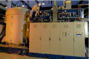
Two atmospheric electrolysers, each at 200 Nm3/h
(photo: Norsk Hydro)
|
|
Norsk Hydro
|
|
|
|
|
Alkaline electrolysers
In alkaline electrolysers a liquid electrolyte is used typically a 25% potassium hydroxide solution.
Hydrogen production using alkaline electrolysers is long-established in Norway. At Norsk Hydro, industrial water electrolysis of hydrogen for the production of ammonia was carried out from 1928 to 1988.
Norsk Hydro Electrolysers (NHE) is today a leading producer of alkaline electrolysers. Some of NHEs electrolysers have an efficiency of over 80% (high heating value). Efficiency is an important factor in electrolysis because the use of energy (~4.5 kWh/NM3H2) makes up a significant portion of the costs at an electrolysis plant. (How much will depend on the cost of the electricity. NHE estimates approximately 2/3 of operating expenses as a rule of thumb.) Electrolysers are most effective when running on a low production rate, due to low current density. Optimum economy of operation will depend both on current density, cost of production materials and the demands for H2 production.
NHE and Gesellschaft für Hochleistungwasserelektrolyseure (GHW) have developed a compact electrolysis system that can produce hydrogen equivalent to the energy supply of a standard gasoline station. These electrolysers operate under pressure, and the product is hydrogen under moderate pressure (30 bar).
Another leading manufacturer of electrolysers, Stuart Energy, has also made a small prototype of a home garage electrolyser with compressor and everything else inside a small gray box.
Polymer electrolyte membrane (PEM) electrolysers
Another type of electrolyser utilises polymer membranes as electrolytes (PEM). Much of the heavy technological development which is currently going on in PEM fuel cells can be transferred to the electrolysers, which will probably benefit from the mass production of PEM fuel cells.
Several PEM electrolysers are already being sold today, even though this is relatively new technology compared to alkaline electrolysers. Efficiency factors for PEM electrolysers up to 94% are predicted, but this is only theoretical at this time. Today, the efficiency factors for PEM electrolysers are lower than for the best alkaline electrolysers. PEM electrolysers function very well with renewable energy systems where the amount of electricity varies greatly. Generally speaking, PEM electrolysers are best suited for small plants, especially plants with varying output, while alkaline electrolysers are clearly an advantage in larger systems which are connected to the power grid.
Steam electrolysers
A third type of electrolysers is the so-called steam electrolysers. These use a ceramic ion-conducting electrolyte. Steam electrolysers can reach a very high efficiency factor, but are currently not commercially feasible.[NYTEK 2000] A tubular steam electrolyser, which should also be able to be run in a fuel cell stack (fuel cells connected in a series), are under development at Lawrence Livermore National Laboratory. Another type of steam electrolyser is the German Hot Elly; this system can reach an efficiency of 92%. [NREL 2000]
2.2.2.2. Photoelectrolysis
Instead of first converting sunlight to electricity and then using an electrolyser to produce hydrogen from water, it is possible to combine these two steps.
The photovoltaic cell combines with a catalyst, which acts as an electrolyser and splits hydrogen and oxygen directly from the surface of the cell. This can quite realistically be a commercially viable means of producing hydrogen. The advantage with these systems is that they eliminate the cost of electrolysers and increase the systems efficiency. Tests performed outdoors with silicon based cells have shown an efficiency of 7.8% in natural sunlight. Research is being done to increase the efficiency factor and the life span for such cells.[DOE 2000], [Turner 1999]
2.2.2.3. Thermal decomposition of water
In a thermal solar power plant with a central collector such as Solar Two, a 10 MW power plant in California, the temperatures can reach over 3,000ºC. By heating water to over 2,000ºC, it is broken down into hydrogen and oxygen. This is considered to be an interesting and inexpensive method of producing hydrogen directly from solar energy. Research is also being done on the use of catalysts to reduce the temperature for dissociation. One central problem is the separation of gases at high temperatures to avoid recombining. The efficiency factor is uncertain.
2.2.2.4. Gasification of Biomass
|
|
|
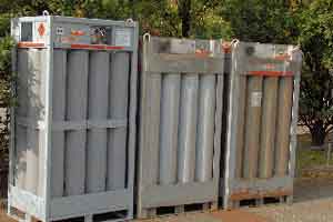
Compressed hydrogen is sold on the market and can be bought from most gas retailers.
|
|
|
|
|
|
Hydrogen can also be produced by thermal gasification of biomass such as forestry by-products, straw, municipal solid waste and sewage.
The amount of hydrogen in biomass is about 6-6.5 weight percent compared to almost 25% for natural gas.[PYNE 8/1999] The processes involved in producing hydrogen from biomass resemble the processes in production from fossil fuel. Under high temperatures, the biomass breaks down to gas. The gas consists mainly of H2, CO and CH4 (methane). Steam is then introduced to reform CH4 to H2 and CO. CO is then put through the shift process to attain a higher level of hydrogen. The by-product from this process is CO2, but CO2 from biomass is considered neutral with respect to greenhouse gas, as it does not increase the CO2 concentration in the atmosphere. The mixed gas can also be used in fuel cells for electricity production. Compared to conventional processes for production of electric energy from biomass or waste, integrated gasification fuel cell systems are preferable. Electrical efficiency over 30% is possible for these systems. This is not possible using traditional technology. [NYTEK 2000]
Gasification reactors have been developed to produce methanol from biomass. Several of these can be used in hydrogen production. Especially those that use air instead of oxygen are economically feasible. [Ogden & Nitsch 1993] Another process which is under development at NREL in the USA is to put the biomass through pyrolysis where it turns into bio-oil. This oil can be converted into hydrogen and CO2 by reforming. The bio-oil, as with fossil oil, is made up of different elements. These can be broken down into various valuable products, including hydrogen. Another advantage with bio-oil is that it reduces the need for transport of large quantities of biomass. Smaller pyrolysis centres which make bio-oil can be set up near the biomass, and the bio-oil from these can then be transported to a hydrogen station by an oil tanker truck, for example. The bio-oil can be stored at the station and reformed to hydrogen as needed. This, in addition to the sale of by-products, can make producing hydrogen from biomass competitive with producing hydrogen from natural gas at large plants. Where there is no infrastructure for natural gas, the bio-hydrogen may be cheaper than hydrogen from natural gas.
2.2.2.5. Biological production
Photosynthesis is the basis for almost all life on earth. The first step in the photosynthesis involves splitting water into oxygen and hydrogen.
The hydrogen is then mixed with carbon dioxide and turned into carbohydrate. Decomposition of water using solar power is obviously not a new idea, but in fact a process which started practically before the age of dawn, and which was the basis for the creation of the earths atmosphere, and consequently the basis of almost all life on this planet. It is also the most common biochemical process on earth. Plain sunlight cannot directly break water down, but with the help of special pigments in organisms that engage in photosynthesis, the energy in sunlight can be utilised. As mentioned earlier, hydrogen which is created by photosynthesis is usually spontaneously changed into a carbohydrate. But there are some micro-organisms which are capable of releasing hydrogen freely into the air. This was discovered in 1896 when a culture with the blue-green algae Anabaena was stored in a sealed jar and exposed to sunlight.
In theory, algae can produce hydrogen with an efficiency of up to 25%. The problem is that during this process, oxygen is also produced. The oxygen inhibits the hydrogen-producing enzyme hydrogenase, so only small amounts of hydrogen are actually produced.
A research team at Berkeley University in California and the National
Renewable Energy Laboratory has shown that by starving the green algae Chlamydomonas reinhardtii of sulphates, the algae cannot maintain a protein complex which is necessary to produce oxygen during photosynthesis. The alga resorts to an alternative process whereby hydrogen is released. After 4 days of producing hydrogen, the algae are allowed to take up the normal photosynthesis process to build themselves back up again. Even though this can be repeated many times with the same algae, in a production plant it would be best to replace algae cultures from time to time so as to maintain a fresh and optimal culture for production. Algae have a very high content of protein, and can be used for example as animal feed after being used in the hydrogen production process.
The research team achieved an average efficiency of around 10%, which is a marked increase from previous attempts. [Science 2000] Focus is now being placed on developing the actual process, as well as equipment which is suitable for technical production and selection of the right algae strains. Production tests outside of the laboratory will be decisive for the ability to develop cheap and effective production plants. Investment costs are expected to cover almost 90% of the expenses involved in this type of production. [Benemann 1998]
The bacterium Rodobacter speriodes has quite successfully been used in the production of hydrogen from organic waste from fruit and vegetable markets. The bacterium has also been tested on sewage with promising results. The process is presently still in the laboratory stage, and a good bit of work remains to increase cost efficiency and general feasibility.
The Institut für Bioverfahrenstechnik in RWTH-Aachen in Germany has developed two different bioreactors that produce hydrogen based on whey from dairy products.
Some of the research in photobiological hydrogen production is based on genetic manipulation of micro-organisms which could collide with environmental issues.
2.3. Use of hydrogen
Hydrogen is used industrially in many processes. The artificial fertiliser and petroleum industries are currently the heaviest users of hydrogen.
Various technologies for use of hydrogen in energy and transportation are presented in the following. Fuel cells are particularly important here. A general review of the most important fuel cell types are presented, as well as a brief description of other technologies involving hydrogen. The final section will look at storage and transportation of hydrogen.
2.3.1. Fuel Cells
|
|
Figure 8
How a PEM fuel cell works.
|
|
|
|
|
|
When hydrogen is burned, there is a reaction between the oxygen and hydrogen which results in water, while energy is released in the form of heat. In a fuel cell, the process is split in two. The two processes take place on each respective side of the electrolyte which keeps the gasses separated, but which transports ions
The negatively charged electrons move in an outer electrical circuit. With this apparatus a portion of the chemical energy is converted directly to electric energy. Theoretically, 83% of the energy can be generated into electricity. In reality, the efficiency is lower, but compared to traditional technology, the fuel cell is very efficient.
The fuel cell was first discovered by Sir William Grove, and patented in 1839. In the section about Daimler Chryslers fuel cell car, Necar 4, there is a comparison of a hydrogen fuel cell car, a diesel car, and a car run on gasoline based on the same car model and driving test. A similar comparison is presented in the section describing Toyotas fuel cell cars.
A fuel cell is, in principle, quite like the cell in a normal battery. The most important difference is that, while battery cells run out of power eventually because the energy stored in them is exhausted, fuel cells continue to produce electricity as long as there is a supply of fuel. As an example, the following is a brief description of a PEM fuel cell.
A PEM fuel cell consists of four basic elements:
The anode is the negatively charged electrode in a fuel cell. In the anode, electrons are released from the hydrogen molecules so they can operate in an external electrical circuit.
The cathode is the positively charged electrode. In the cathode, electrons are conducted from the external electrical circuit to the catalyst where they react with oxygen and hydrogen ions turning into water.
The electrolyte is the proton exchange membrane. This is a plastic (polymer) which is specially treated to be able to conduct positively charged ions (protons). The membrane stops the electrons from crossing over.
The catalyst is a material which makes the reactions at the electrodes occur more rapidly, but which in itself does not participate in the reactions. The most common catalyst is platinum. Platinum is pulverised and evenly distributed around small carbon particles, in order to use the least amount of platinum and to create the greatest surface area possible.
In addition to these four elements, a conducting plate or wire providing electrical contact between the electrodes is needed.
A PEM fuel cell operates by putting a hydrogen molecule in contact with the platinum catalyst, splitting it into two hydrogen ions (protons) and two electrons. The electrons are conducted by the electrode to the external circuit where they can power for instance an electrical motor. They are then fed onward to the cathode where oxygen from the air splits into two oxygen atoms when it comes in contact with the catalyst. Two hydrogen ions combine with one oxygen atom and two electrons from the conductor, to create a water molecule The reaction in a fuel cell produces only about 0.7 volts, so several fuel cells are connected in a series to attain a functional level of output. Fuel cells connected together are called a fuel cell stack.
2.3.1.1. Fuel cell system
Smaller systems generating less than 100 watt do not always require cooling or air pumps. But in systems greater than 100 watt, a good deal of extra equipment is needed.
The term fuel cell system is often used in this case. Just as when referring to a car engine, this means the entire system of air supply, fuel system, cooling system and pumps which are necessary for the engine to operate properly. The same applies for a fuel cell system or a fuel cell engine; it needs cooling, air supply, etc. Certain fuel cells also use compressors and intercoolers, and again, just as with cars, it is important that the entire system is optimised for top performance.
There are several types of fuel cells with different characteristics and uses. Fuel cells are classified in the same way as electrolysers, usually according to the electrolyte that is used, ref. Table 1.
2.3.1.2. Alkaline fuel cells (AFC)
Alkaline fuel cells were used as the power supply on the Apollo flights, and are currently used onboard NASAs space shuttles.
The main developers of the alkaline fuel cell have been F.T.Bacon, Energy Conversions, Pratt Whitney and Elenco. Elencos technology and patents have been taken over by Zetek. This company has supplied fuel cells to, among others, a hydrogen-driven London taxi and a passenger boat in Bonn. One advantage with this type of fuel cells is that it is possible to use an inexpensive catalyst, such as nickel.
Alkaline fuel cells are sensitive to CO2. If air is used instead of pure oxygen in the fuel cells, the air has to be cleansed of CO2. Another disadvantage is that the electrolytes are liquid and corrosive.
2.3.1.3. Phosphoric acid fuel cells (PAFC)
|
Five PAFC fuel cells in Alaska. The system generates 1 MW.
|
|
|
|
|
|
|
Phosphoric acid fuel cells have been under development since early in the 1960s, and are used world-wide.
This type of fuel cell uses, as the name indicates, phosphoric acid as the electrolyte and is CO2 tolerant. The electrical efficiency of PAFC systems is relatively low, around 35-45%. In addition excess heat is produced which is often used for heating.
International Fuel Cells (IFC) sells PAFC commercially, and has sold more than two hundred 200 kW phosphoric acid fuel cell systems. Combined, these systems have been in operation for more than 4 million hours. [King 2000] [IFC 2001] IFC is planning to stop the production of PAFC fuel cells, and will instead produce a 150 kW PEM fuel cell system starting in 2003.
2.3.1.4. Solid oxide fuel cells (SOFC)
|
|
|
Solid oxide fuel cells integrated with turbines can reach an extremely high degree of efficiency compared to traditional power generation technology. The picture was taken during assembly of a 220 kW hybrid turbine in California, the first of its kind. Further description is found in Chapter 4.
|
|
Siemens Westinghouse
|
|
|
|
The solid oxide fuel cell is a high temperature fuel cell. The electrolyte consists of an oxide, usually of zirconium oxide, with some added yttrium oxide. This oxide conducts oxygen ions at high temperatures.
The maximum electrical efficiency of a solid oxide fuel cell driven by hydrogen is estimated at 60%. In other words, the fuel cell can manage to convert 60% of the fuel energy in the hydrogen into electric power.
There are still certain problems with the solid oxide fuel cell. In order to achieve enough conductivity, it is necessary to operate at temperatures close to 1,000ºC. There have been considerable difficulties with materials at this high temperature and research is being done both to develop new, more stable materials for these temperatures, and to decrease the operational temperature.
One leading company in the development of solid oxide fuel cells for stationary power production is Siemens Westinghouse (SW). In 1997 they installed 100 kW fuel cells in Arnhem in The Netherlands. The fuel cell stack was driven by natural gas and was in operation for 16,612 hours. The most impressive aspect with this fuel cell stack was that, when inspected as to how it withstood the period of operation, it was found to be in perfect condition without any signs of wear. The cell stack has been moved to Germany, and has now been operating for over 20,000 hours. It produces 110 kW of electricity and the total electrical efficiency factor is 46%. In addition, it supplies 64 kW of heat to the remote heat network. SW currently has several test projects going on, one of which is a 250 kW unit which Shell will install at Kollsnes outside Bergen in Norway. SW will be building a production plant for SOFC in Pittsburgh, USA, and will start sale of SOFC systems with capacities ranging from 250 to 5,000 kW towards the end of 2003. [Westinghouse 2002]
Two of the other central companies which are working on developing solid oxide fuel cells are Rolls Royce and Sulzer. There have been two large SOFC projects in Norway: Mjølner and Norcell. Both of these were shut down a few years ago, but Prototech in Bergen is still working on developing the SOFC. In Denmark there is relatively heavy investment in SOFC. The research is being done at Risø and Haldor Topsøe [Nytek 2000], based on European co-operation.
The major supplier of car components, Delfi, together with BMW, is developing a solid oxide fuel cell which will replace the car battery in BMWs future models. These solid oxide fuel cells will use the cars own fuel to produce electricity, providing a much more efficient utilisation of the fuel than todays combustion engine and dynamo system
2.3.1.5. Proton exchange membrane (PEM) fuel cells
|
|
Figure 2
Use of platinum per kW effect of fuel cells. The figure reflects the considerable reduction in use of expensive platinum over the last decade.
Source: Ford (2001)
|
|
|
|
|
|
Proton exchange membrane (PEM) fuel cells are often called solid polymer fuel cells (SPFC). We have however decided to use PEM as this is the most commonly used term.
PEM fuel cells were mainly developed by General Electric (GE) in the period between 1959 and 1982. Ballard in Canada began development of PEM fuel cells in 1983 and has since contributed greatly to its development after GE closed down its fuel cell project. Development of better membranes, less amounts of platinum as a catalyst and more effective handling of water exhausts has made the PEM a leading fuel cell type.
The electrolyte in a PEM fuel cell consists of a membrane of solid polymer which allows protons to be transferred from one side to the other. PEM fuel cells operate at 80ºC which makes it well suited for supplying a regular home with electricity and hot water. PEM is much more efficient than batteries for transportation purposes and mobile power supplies. First and foremost, PEM are light and sturdy. The fact that the electrolyte is solid makes it safer. PEM fuel cells respond quickly to changes in load, a characteristic that improves vehicle acceleration. PEM technology is also suitable for mass production. One disadvantage with the PEM fuel cell, however, is the use of platinum as a catalyst, but the amount of platinum has been dramatically reduced in recent years (see figure), and there seems to be great potential to reduce it even more.

|
PEM fuel cells are becoming lighter and more compact. Shown here is an 80 kW fuel cell stack which was presented in January 2000.
|
|
|
|
|
|
|
PEM fuel cells can tolerate CO2 but are sensitive to CO pollution, which can result in reduced efficiency. This is a problem for those attempting to use reformed hydrocarbons as fuel, but not when pure hydrogen is used.
Ballard is currently working with Ford and DaimlerChrysler. Other core developers of PEM fuel cells are General Motors, Toyota, HPower, Panasonic, International Fuel Cells, NovArs, DeNora, and Plug Power to name a few.
The likelihood of increasing the efficiency, output/weight and output/volume ratios for this type of fuel cell by using other materials is great. On the other hand, the PEM is already competitive in its existing form in most areas. Mass production of the PEM fuel cells would also make it competitive pricewise.
2.3.1.6. Molten Carbonate Fuel Cells (MCFC)
Molten carbonate fuel cells use a molten alkali carbonate as an electrolyte.
This type of fuel cell was designed in the 1940s and demonstrated in the 1950s. Development of MCFCs has moved slowly. [Blomen 93] There are several MCFC installations, but there have been serious problems with materials used in this type of fuel cell. Important producers are Fuel Cell Energy in USA and Motoren-und Turbinen-Union (MTU). MTU expects to start limited series production and put it on the market at competitive prices starting in 2004. [Hyweb 2001][MTU2001] MTUs system operates at 600ºC. This is a fairly low temperature for MCFCs, and affords less stress on the materials. The electrical efficiency for the system is noted at 50%. In addition, the unit produces pressurised steam at 400ºC. The life expectancy is estimated to be 20,000 hours. [MTU 2001]
2.3.1.7. Direct Methanol fuel Cells (DMFC)
Direct methanol fuel cells are a variation of the PEM type, and as the name indicates, use liquid methanol without initial reforming.
There has been intense R & D on this type of fuel cell these last few years. The efficiency rating, which was previously very low, has increased somewhat. Just a short while back DaimlerChrysler introduced a go-cart that uses this type of fuel cell.
The biggest problem with methanol is that it contains carbons that are released mainly as CO2 when its used as fuel. Methanol is also very poisonous.
2.3.1.8. Regenerative fuel cells
Simply put, this is a fuel cell which produces electricity and heat, and which can reverse the process.
When supplied with electricity, it can be used in electrolysis of water to produce hydrogen and oxygen. In other words the same unit is used for two functions, possibly saving on weight and costs compared to a system with separate fuel cells and electrolyser.
The efficiency rating for the one function in a regenerative fuel cell is not necessarily any less than for dedicated fuel cells or electrolysers. But the catalyst in the system cannot be optimised for both. In other words, efficiency is not at its height in both processes. Therefore, a system that will primarily produce hydrogen, for example, should be at peak performance for electrolysis. Regenerative fuel cell systems are most often based on PEM technology.
Table 1
Some common fuel cell types and their uses. (CHP: Combined Heat and Power)
| Type |
Area of use |
Electrolyte |
Temperature ºC |
| Alkaline (AFC) |
Space travel, transportation |
Alkaline |
50 200 |
| Direct Methanol (DMFC) |
Transport, mobile equipment |
Polymer |
80 - 200 |
| Proton Exchange Membrane (PEM) |
Space travel, transportation, small CHP, mobile equipment |
Polymer |
50 80 |
| Phosphoric Acid (PAFC) |
CHP, power plants |
Phosphoric acid |
190 210 |
| Molten Carbonate (MCFC) |
CHP, power plants |
Molten carbonate |
600 650 |
| Solid Oxide (SOFC) |
CHP, power plants |
Solid oxide |
600 1,000 |
2.3.2. Burning hydrogen
Hydrogen can also be burned in the normal way using oxygen or air, and the heat resulting from the combustion can be used for either heating, cooking, turbines, boilers or in combustion engines.
2.3.2.1. Combustion technology
Because of hydrogens high burning temperature, large amounts of NOx will be released under standard combustion methods.
. It is therefore better to turn to other processes which have lower NOx emissions. Catalytic burners use a catalyst to reduce the burning temperature, thereby reducing the creation of NOx. There are several burners which use diffusion (i.e. primus stove principle) for low NOx burning of hydrogen. [Nytek, 2000]
Up to 15% H2 may be added to regular natural gas, without any need to adjust conventional burners.[Hart, 1997]
2.3.2.2. Hydrogen engines
Rudolf Erren studied the use of hydrogen in combustion engines in the 1920s and developed his own method of conversion often referred to as the Erren engine.
Erren and his colleagues are supposed to have converted somewhere between 1,000 and 3,000 cars, busses and trucks to hydrogen. In the USA in the 1970s, Roger Billings converted a Model A Ford to hydrogen when he was just 16 years old. [Hart 1997] Billings based his conversions on Errens concepts. He and Frank Lynch later started Hydrogen Consultants (which has now changed its name to Hydrogen Components, Inc. (HCI)). HCI has developed a special injection system and converts cars to hydrogen. The company has converted several cars, including a Mazda with a wankel motor, a Winnebago RV that used hydrogen as both fuel and energy source for cooking and heating, as well as a large peace of mining equipment. Some of these engines have reached efficiencies of 42%, and may be a cheaper alternative to fuel cells in the short term.
Of the larger car manufacturers, in particular BMW has been working on combustion engines using hydrogen.
Engines for stationary production of electricity and heat from natural gas can easily be converted to run on hydrogen.
2.3.2.3. Turbines
There are currently several coal-powered gas plants that operate on coal gasification (IGCC), which uses considerable amounts of hydrogen in the fuel.
The combustion chamber concept developed for syngas from coal gasification is well suited for fuel with a high content of hydrogen (syngas: synthesis gas; mixture of carbon monoxide and hydrogen). The usability of hydrogen in turbines has been verified by several turbine manufacturers, notably GE. Currently cheaper than fuel cells, turbines may be considered a transitional technology.
Norsk Hydros Hydrokraft concept was based on electric power production with turbines and hydrogen. This is elaborated on in the section on removal of CO2 in Chapter 4.
2.3.2.4. Hybrids
By integrating solid oxide fuel cell technology with turbines, the electrical efficiency of a gas power plant can reach up to 80% under optimum conditions.
Fuel cells alone have the potential to utilise 60% of the energy in the fuel. The rest is lost in the form of low quality heat, but also because the fuel cells are not capable of utilising all the fuel. The excess fuel in the exhaust gas can be used however with the help of gas turbines. Such a plant would still produce NOx unless pure O2 is used in the afterburner, but to a lesser degree than in a conventional power plant.
Siemens Westinghouse has started a 220 kW SOFC micro turbine hybrid system at the University of California in Irvine. This is the first of its kind and the efficiency is 52-53%. A 550 kW system is under development.
2.4. Storage of hydrogen
If hydrogen is to be used on a large scale basis, storage is a key problem. In vehicles for instance, it must be possible to store enough hydrogen to allow for the same driving distance as todays cars.
In the energy sector the ability to store the hydrogen effectively, quickly and inexpensively is most important. This chapter will take a look at hydrogen storage with special focus on storage in vehicles.
Hydrogen is a substance with high energy content compared to its weight. This is the reason that hydrogen is naturally the first choice in space travel and very well suited for air travel. On the other hand, the energy content compared to volume is rather low. This poses greater challenges with respect to storage compared to storage of gasoline which is a liquid.
The US DOE has determined that an energy density of 6.5 weight percent hydrogen and 62 kg hydrogen per m3 must be achieved, in order for a hydrogen storage system of appropriate weight and size to facilitate a fuel cell vehicle driving distance of 560 kilometres.
There are basically three options:
- hydrogen may be compressed and stored in a pressure tank
- hydrogen may be cooled to a liquid state and kept cold in a properly insulated tank
- hydrogen may be stored in a solid compound
Various strategies for storage are described in the following section.
2.4.1. Compressed hydrogen
Storing hydrogen under pressure has been done successfully for many years.
The three main types of tanks are:
- Steel
- Aluminium core encased with fibreglass (composite)
- Plastic core encased with fibreglass (composite)
In stationary systems where weight and size are not decisive factors, steel tanks are a good solution, but for vehicles, traditional pressure tanks are problematic regarding both weight and volume. There has been considerable breakthrough the last few years in the development of a new type of composite tank which can store hydrogen at 350 bar pressure and at the same time meet the current safety standards. This type of tank has a storage capacity of 10-12 weight percent hydrogen [DOE, 2000], whereby the weight of the tank no longer is a problem. Progress is also being made on tanks which can store hydrogen at 700 bar pressure. This will reduce the tank volume, which is necessary to achieve the desirable driving distance. Light weight composite tanks which utilise space better than the usual cylindrical tanks have also been designed.
Special H2 compressors are normally used to pressurise the hydrogen. If pressure electrolysers are used to supply compressed hydrogen, the process of compressing could be reduced or eliminated all together depending on what pressure level is needed. This would be a more efficient system, and a simpler and less expensive solution.
2.4.2. Liquid hydrogen
|
|
|
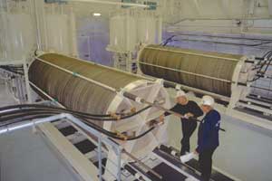
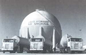
NASA has been a heavy user of hydrogen in space programs for several decades. This shows a storage tank for liquid hydrogen and hydrogen tank trucks. (photo: NASA)
|
|
NASA
|
|
|
|
Hydrogen can be stored as a liquid (LH2) at 20 K (-253º C) in super insulated tanks.
LH2 is particularly interesting for long distance transportation purposes and as fuel in spacecraft and airplanes. A great deal of experience has been accumulated over the years when it comes to the usage and handling of LH2. In order to cool the hydrogen down, energy equalling 30-40% of that in the fuel is needed. Development of a new cooling process that would cut the energy use in half is considered feasible. [Nytek 2000] LH2 is especially well suited for use in air and space travel, where its characteristics rate it higher than any other fuel. Today, LH2 is the most frequently used fuel within space travel.
BMW has studied use of liquid hydrogen in combustion engines in cars for over 20 years and says that using liquid hydrogen in automobiles is a good alternative. The German company Linde has developed a tank for liquid hydrogen where the cold from some of the liquid hydrogen is used to cool down the insulation surrounding the tank; this is done with cooling elements. This way the tank keeps the hydrogen in a liquid state for up to 12 days.[Hyweb, 2000] This type of tank is now being tested and will probably be installed in BMWs hydrogen cars among others.
2.4.3. Metal hydride
Figure 9
Hydrogen gas moves in toward the interface. There the hydrogen molecule is split into hydrogen atoms which are absorbed by the metal, whereby hydrogen is stored in the metallic matrix.
|
|
|
|
|
|
|
Certain metals and metal alloys have the ability to absorb hydrogen under moderate pressure and temperature, creating hydrides. Hydride is a compound which contains hydrogen and one or more other elements.
A metal hydride tank contains, in addition to a heat manipulation system, granular metal which absorbs the hydrogen like a sponge absorbs water. The heat system draws heat away when hydrogen is filled into the tank, and applies heat when the hydrogen is taken out of the tank.
The hydrogen is released from the metal hydride when heat is applied. This heat may, for example, be excess heat from the fuel cells.
A metal hydride tank is considered to be a very safe fuel system in the event of a collision because the loss of pressure in a punctured tank will cool down the metal hydride, which will then cease to release hydrogen.
Several metal hydrides are available commercially, representing a good solution for hydrogen storage where the weight factor is not a problem. For vehicles, the problem with metal hydride is the high weight compared to the amount of hydrogen stored. The problem of weight has still not been solved in spite of extensive research. Researchers are therefore trying to think in new directions, by trying to lighten the alloys for one, and finding methods of packing the hydrogen in higher concentrations.
At the Institute for Energy Technology at Kjeller in Norway (IFE), work is being done on storing hydrogen in alloys with extremely densely packed hydrogen atoms, which allows for higher concentrations.
Work is being done on finding cheaper metal alloys which have the ability to absorb large amounts of hydrogen, and at the same time release the hydrogen at a relatively low temperature. The International Energy Agencys (IEA) metal hydride program has a goal of 5 weight percent absorbed hydrogen and hydrogen release at < 100ºC.
NaAlH4 is a promising, reasonably inexpensive metal hydride. With its 4 weight percent hydrogen and 150 ºC release temperature NaAlH4 almost meets the IEA requirements. This metal hydride is now the focus point for development of a hydrogen storage system in the USA, and is also being studied at IFE.
Todays modern PEM fuel cells operate at low temperatures. If the excess heat from the fuel cells is to be used to release hydrogen, it is important that the hydride releases the hydrogen at the same temperature. The energy efficiency of the system will be lower, and the system more complex, if extra heat must be generated to remove the hydrogen from the tank.
Metal hydride can also be used for compressing hydrogen.
2.4.4. Hydrogen in carbons
Certain carbons have a very large surface area and research has been going on for several years to try to store hydrogen in these materials.
According to several research groups, carbon nanostructures such as nanofibers, nanotubes and fullerenes have shown promising abilities to absorb hydrogen.
Intense efforts are being made to develop methods for producing single-walled nanotubes economically on a large scale. Use of laser technology has made it possible to produce a high percentage of nanotubes with the exact diameter and level of purity needed. Production of nanotubes is growing rapidly. Nanotubes have several interesting qualities which to good effect can be used in hydrogen technology. For example, they can be used in fuel cells, ultra condensers for efficient storage of retardation energy and hydrogen storage. An American research group has repeatedly achieved storage of 7.5 weight percent hydrogen in single-walled nanotubes at room temperature. In these experiments the nanotubes had been subjected to ultrasound. Sources say it will be possible to reach a somewhat higher storage capacity in the not too distant future. Presently, work is done to scale up these experiments. [Dillon, 1999]
It would be appropriate here to mention that there is a great deal of disagreement surrounding the storage capacity of carbons. For instance, a German research team has done very thorough attempts at repeating the above mentioned American experiment, and still only achieved a very low storage capacity for hydrogen. [Haluska 2001]
2.4.5. Methanol
Methanol (CH3OH) has a high content of hydrogen which can relatively easily be extracted by reforming.
There are those that say methanol would be a good transitional fuel solution for smaller cars. The advantage of methanol is that it is liquid under normal air pressure and room temperature, and has a high content of hydrogen compared to other fossil fuels. Methanol is produced from natural gas by steam reforming the natural gas into synthesis gas. In a methanol car with a reformer, the methanol will be reformed into hydrogen which is then used in the fuel cell. The energy loss in these two processes is high and the system efficiency therefore low.
Methanol (wood spirit) is a very poisonous liquid with many similarities to ethanol. Methanol has been found to be cancer-causing, corrosive and could pollute the ground water. Several large oil companies have very clearly given the signal that they will not develop a methanol infrastructure because the safety risks are too great.
|
|
Figure 10
Hydrogen, gasoline and methanol compared as to complexity of the fuel system and infrastructural costs. (source: Sandy Thomas)
|
|
|
|
|
|
Several environmental organisations, including Bellona, will actively oppose building such an infrastructure. In addition to the directly damaging effects of methanol, a temporary methanol infrastructure would also delay development of the hydrogen infrastructure. It would require heavy investment, while the methanol-fuelled cars would remain on the road for several decades. Another drawback with a methanol infrastructure is the fact that fuel cell cars which cannot use methanol directly, must be equipped with an expensive reformer. It would most likely take several decades before direct methanol fuel cells (DMFC) could be used in regular vehicles. Costs are therefore placed on the consumer, while making fuel cell technology more expensive than necessary.
It has often been stated that methanol can be transported and handled just like gasoline, but this is not true. Methanol is very corrosive, and a methanol spill could cause severe damage to the environment. Methanol mixes with water and is almost impossible to reclaim once spilled.
A fuel cell car with a methanol reformer will have high levels of CO2 emissions probably somewhere between 60% and 70% of a comparable gasoline car with combustion engine.[NOU 1998:11] There would also be hydrocarbon and CO emissions. Increased distribution of methanol will pose substantial risk of poisoning both humans and animals. Because of the low system efficiency and high emissions compared to hydrogen and electricity, methanol will not measure up to the future fuel requirements for vehicles. Methanol therefore cannot be recommended as a fuel.
2.4.6. Gasoline and other hydrocarbons
|
|
Figure 11
Costs of hydrogen compared to gasoline with (EU) and without taxes.
|
|
Source: Norsk Hydro
|
|
|
|
Converting gasoline (alternatively a special blend, a form of naphtha) into hydrogen-rich gas in cars has also been the subject of much research and development.
Oil companies, having invested enormous amounts of money into a gasoline infrastructure, are especially interested in this option. These temporary solutions offer, as with methanol, less performance and fuel efficiency than solutions based on pure hydrogen. This would also require a very complex reformer which makes it expensive, heavy and unsuitable. It is also very difficult to remove hydrocarbons and CO, and CO destroys the catalyst in PEM fuel cells. This type of reformer would have to operate at such high temperatures that it would also create NOx. Just as with methanol, only to a greater degree, the increased costs are placed on the car owner. The system becomes more complex, making the car more susceptible to technical problems, while efficiency is reduced; in other words, not a very wise choice. Hybrid cars which are already on the market offers the same lower levels of CO2 as would fuel cell cars with gasoline and methanol as fuel. SAABs combustion engine with variable compression (not yet in production), is supposed to have equally low levels of CO2. [Automotive World, 2000]
Table 2
Summary of weight and volume of different tank types. All examples have the same driving distance when using the same type of vehicle.
Source: Ford, 2001 and Quantum, 2001
| Vehicles with equal driving distances per fill-up |
Mass (kg) |
Volume (liter) |
| Gasoline/combustion engine |
50 |
70 |
| Compressed hydrogen (350 bar) / fuel cells |
90 |
320 |
| Compressed hydrogen (700 bar) / fuel cells |
~ 100 |
180 |
| Liquid hydrogen / fuel cells |
45 |
190 |
| Hydrogen in metal hydride / fuel cells |
200-600 |
180 |
2.4.7. Stationary storage
Hydrogen can be stored in pressure tanks, in underground cavities and as a liquid in superinsulated tanks.
All this is standard technology. For storage of very large amounts of hydrogen, the most economical method is underground storage under pressure.[NRF 2001]
The expenses of storing hydrogen in caverns will vary according to the geological formations, but this could be an inexpensive option. The German town of Kiel is supposed to have stored city gas with a hydrogen content of 60-65% in a gas storage hall with a volume of 32,000 m3 under 80-100 bar pressure since 1971.[Winter, 1988] Usable as such underground storage areas may be empty reservoirs, aquifers, caverns or empty cavities in salt formations.
2.5. Transport of hydrogen
2.5.1. Pipelines
In the USA there is 720 km of hydrogen pipeline network and in Europe about 1,500 km. Over great distances, pipeline transport of hydrogen could be an effective way of transporting energy.
The energy loss in an electric power grid can be up to 7.5-8% of the energy it is transferring. This is about double of what is needed to feed gas through a pipeline of the same length.
Hydrogen pipes that are in use today are constructed of regular pipe steel, and operate under pressure at 10-20 bar, with a diameter of 25-30 cm. The oldest existing system is found in the Ruhr area. It is 210 km long and distributes hydrogen between 18 producers and consumers. This network has been in use for 50 years without any accidents. The longest hydrogen pipeline is 400 km and runs between France and Belgium.
With little or no changes, the majority of existing steel natural gas lines can be used to transport mixtures of natural gas and hydrogen. It is also possible, with certain modifications, to use pure hydrogen in certain existing natural gas lines. This depends on the carbon levels in the pipe metal. Newer gas pipelines such as those in the North Sea, have low carbon content and are therefore suitable for transporting hydrogen. If the speed is increased by a factor of 2.8 to compensate for hydrogen having 2.8 times lower energy density per volume than natural gas, the same amount of energy can be moved. The fact is that by using efficient hydrogen technology such as fuel cells, etc., the same amount of transported energy will yield increased output at final consumption.
In the natural gas distribution network, pressure is low, around 4 bar, and so cheaper plastic pipe is usually used. PVC (Poly Vinyl Chloride) and the newer HDPE (High Density Poly Ethylene) are too porous and not usable for transporting hydrogen. [Princeton, 1997]
Gas pipelines, in addition to being used for transportation, can also be used to store great quantities of hydrogen. By regulating the pressure in the pipes, it is possible to use the large volume a pipeline offers as storage during peak situations.[Winter, 1988]
Natural gas which is transported from the Norwegian shelf to the Continent in pipelines can hold an additional 15% hydrogen. This hydrogen can be produced in Norway with CO2 depositing. The gas which is transported can consequently be sold at a higher price, while carbon taxes in the receiving country must be comparably reduced. In this way, the income from the hydrogen will contribute more added value to the Norwegian society. The mixture hydrogen/methane can be used in the same way as natural gas, and will produce a higher combustibility factor because of the higher energy content.
2.5.2. Transport of liquid hydrogen
Liquid hydrogen (LH2) is hydrogen which has been cooled below -253ºC. The cooling process requires a great deal of energy, but for long-distance transportation and as fuel in certain applications used in air and space travel, LH2 still has obvious advantages over other fuels.
2.5.3. Roadway transportation
Hydrogen can be shipped with tank trucks in both liquid and compressed states. Several companies currently deliver these types of tank trucks.
2.5.4. Ocean transportation
Hydrogen can be transported as a liquid in tank ships. These are not too different from LNG tankers, aside from the fact that better insulation is required to keep the hydrogen cooled down over long distances. The Japanese WE-NET and the German-Canadian Euro Quebec have reported on the use of such tanks. The evaporated hydrogen may be used as fuel onboard.
In 1990, the German institute for materials research declared that LH2 could be given the same safety rating as LPG and LNG, and transport of LH2 into German harbours was approved.
2.5.5. Air transportation
There are several advantages in transporting LH2 by air rather than by ship. LH2 is lightweight and the delivery time is much shorter, and evaporation is therefore not a big problem. Studies on this have been done by CDS Research Ltd. in Canada, with support from the WE-NET program.
|
